Both currently available prpl Reference boards 'Freedom' as well as 'OSPv2' are using the same IOT solution from SiLabs, an EFR32MG.
This page describes the steps necessary to enable Thread on OSPv2. Please find the instructions for Freedom here .
Board Information
The EFR32MG21 is located together with the Wifi chip, an optional 5G modem, and the GNSS receiver on a separate daughter board (DB) that is connected to the main board (MB) via 2 highspeed connectors. You can find the version of the DB as well as the version of the MB printed on the respective PCB. A typical configuration is MB_V03 combined with DB_V02.
Please note that for OSPv2 shipped before October 2024 with a daughter board DB_V02 version the bootloader does not allow in device flashing, so the bootloader will initially need to be flashed via a Silabs Debugger. Once an appropriate bootloader has been flashed, upgrading from the Linux command line will be possible. Please see further down on this page. OSPv2 shipped in October 2024 and later have been pre-flashed with a EFR32MG21 bootloader that will allow to upgrade the EFR32MG21 from the OSPv2 Linux command line.
PIN configuration
There are 2 versions of the DB available DB_v02 which was shipped till ~Dec2024 and DB_v03 which will be shipped in 2025.
DB_V02 Pin configuration
| Host Mxl25641 (MB_V03 + DB_V02) | |
|---|---|
| GPIO39 | EFR32 Reset |
| GPIO61 | EFR32 recovery |
| GPIO66 | UART1 RX |
| GPIO67 | UART1 TX |
| EFR32MG21A020F512IM32 | |
|---|---|
| PA05 | UART TX |
| PA06 | UART RX |
| PB0 | Recovery |
| RESETn | Reset |
Coexistence:
IOT and Wifi do share the same 2.4Ghz ISM band. This can cause performance issues for IOT. In order to address this issue a coexistence solution can be used. The Wifi PTA (Packet Traffic Arbitrator) manages the airtime between Wifi and IOT using a 3 Wire control (using GPIO pins). For OSPv2 these are the GPIO Pins used:
| Mxl31712 | EFR32MG21 | |
|---|---|---|
| Request | IO10 | PD02 |
| Priority | IO8 | PD03 |
| Grant | IO07 | PC01 |
- Request: The IoT device signals a request for airtime to the WiFi PTA by setting the Request pin high.
- Priority: The IoT device signals a high priority for transmitting a message by setting the Priority pin high.
- Grant: WiFi PTA grants the IoT request by setting the Grant pin low.
Documentation on coexistence for the EFR32MG21 is available here
To enable/disable and check coexistence for the Wifi chip on OSPv2 the following commands need to be executed:
-
Enable coexistence
# iw dev wlan0 iwlwav sConfigMRCoex 1 16 4 0 -
Disable coexistence
# iw dev wlan0 iwlwav sConfigMRCoex 0 16 4 0 -
Check coexistence status
# iw dev wlan0 iwlwav sConfigMRCoex
DB_V03 Pin configuration
will be published once these boards get shipped
OSPv2 CPU governor configuration
Unfortunately it is not possible to to use the EFR32MG21 on OSPv2 in the default board configuration with the CPU governor set to powersave.
EFR32MG21 is connected on OSPv2 with DB_v02 via UART using only RX and TX. To ensure this is connection is working stable the CPU governor has to be set to performance mode:
To set performance mode:

For the next batch of OSPv2 (most likely it will be called OSPv2.1) DB_v03 is used. On DB_V03 RTS and CTS are used for flow control, on that board the CPU governor can be left in powersave. Please note that on DB_V03 the UART on the MXl25641 will change too.
Flashing of the EFR32MG21 Firmware and bootloader via Silabs Debugger
Required tools
-
Si-MB4002A Wireless Pro Kit Mainboard + USB Type C cable: The Wireless Pro Kit Mainboard is a development board for application development and debugging of wireless products. It supports on-board J-Link debugger. It comes with the mini-Simplicity cable which does work on OSPv2 without the 'Debug Adapter Kit'.
- Ordering information: Mouser Europe - Mouser International
- User's Guide
-
For other Silabs debuggers like the BRD4001A a Debug Adapter Kit (SLSDA001A) is required
- Ordering Information: Mouser Europe Mouser International
-
Simplicity Commander a utility that provides GUI and command line access to the debug features of an EFR32 device.
-
J-Link Driver An on-board J-link debugger that enables programming and debugging on the EFR32 device over USB. NOTE: If the J-Link appears as a generic USB BULK device in the Windows device manager, please follow the steps on the Segger WiKi to resolve this issue.
Connect debugger to OSPv2
please use the port called 'mini' on the debugger to connect the ribbon cable, and locate the 10 pin header on OSPv2.
 MB4002A
 ribbon cable connected to the OSPv2 DB; please note the orientation of the cable and the notch
Connect the debugger to your Laptop via a USB cable
Upgrade Bootloader and Firmware of the EFR32MG21 via Commander
Install the J-Link debugger and driver.
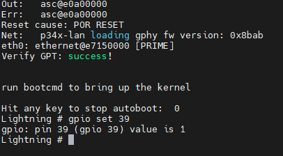
Connect the debugger and power it on before powering on OSPv2. Once you power on OSPv2 make sure you have a console connected, stop the boot process at the bootloader. Put the EFR32 in reset
Lightning # gpio set 39
now unpack Simplicity Commander, and start it

 select your debugger (in this case 440329773)
 select the debug port - Debug Mode
Set it to MINI for the BRD4002A debugger
you may need to set it to OUT when using a debugger that requires the use of the 'Debug adapter'
Erase the flash
 select Flash, then select Erase Chip, ensure that Flash was erased successfully
Select the bootloader and flash it
 select the file bootloader-uart-xmodem_v3.s37 , click Flash, and verify that Flashing completed successfully!
Flash firmware via the debugger
Now you can flash a Firmware of your choice the same way as the bootloader. Make sure the file you select is of file type .s37
You may want to compile the Firmware yourself using Simplicity Studio. There are a couple of precompiled firmware images you can select from